Meshes
Tube
2D tube

FreeFem++ algorithm for the 2D tube mesh generation and generated mesh:
-
tube_2D.edp
-
tube_2D.msh
Overview of the code
//Parameters
//Dimensions
int nn = 10;            //number of nodes by unit
real L = 5.0;           //length
real D = 1.0;           //diameter
//Labels
int input = 1;          //left side
int output = 2;         //right side
int borders = 3;        //borders

//Variables
string filename = "";   //save name
mesh Th;                //mesh

//Mesh
//Border
border gamma1(l=0, L){x=l; y=0.0; label = borders;};
border gamma2(l=0, D){x=L; y=l; label = output;};
border gamma3(l=0, L){x=L-l; y=D; label = borders;};
border gamma4(l=0, D){x=0; y=D-l; label = input;};
//Mesh
Th = buildmesh(gamma1(L*nn) + gamma2(D*nn) + gamma3(L*nn) + gamma4(D*nn));

//Save
//Mesh
filename = "tube_2D";
savemesh(Th, filename + ".msh");
//Parameters
ofstream file(filename + ".dat");
file << "L\t" << L << endl;
file << "D\t" << D << endl;
file << "E\t" << input << endl;
file << "S\t" << output << endl;
file << "B\t" << borders << endl;

//Display
plot(Th, cmm = "Number of triangles = " + Th.nt + ", Length = " + L + ", Diameter = " + D);
3D tube

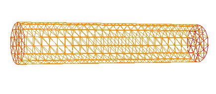
FreeFem++ algorithm for the 3D tube mesh generation and generated mesh:
-
tube_3D.edp
-
tube_3D.msh
Overview of the code
load "msh3"

//Parameters
//Dimensions
int nn = 10;            //number of nodes by unit
real L = 5.0;           //length
real D = 1.0;           //diameter
//Labels
int input = 1;          //left side
int output = 2;         //right side
int borders = 3;        //borders

//Variables
string filename = "";   //save name
mesh Baseh;             //mesh 2D
mesh3 Th;               //mesh 3D

//Mesh
//Base circle
border C(t=0,2*pi) { x = (D/2.0)*cos(t); y=(D/2.0)*sin(t); label=1;}
//Base mesh
Baseh = buildmesh(C(pi*D*nn));
//Cylinder 3D
int[int] rup=[0,output],  rdown=[0,input], rmid=[1,borders];
func zmin= 0;
func zmax= L;
Th=buildlayers(
    Baseh,
    L*nn,
    coef = 1.,
    zbound = [zmin,zmax],
    labelmid = rmid,
    reffaceup = rup,
    reffacelow = rdown);

//Save
//Mesh
filename = "tube_3D";
savemesh(Th, filename + ".mesh");
//Parameters
ofstream file(filename + ".dat");
file << "L\t" << L << endl;
file << "D\t" << D << endl;
file << "E\t" << input << endl;
file << "S\t" << output << endl;
file << "B\t" << borders << endl;

//Display
plot(Baseh, cmm = "Base mesh");
plot(Th, cmm = "Number of triangles = " + Th.nt + ", Length = " + L + ", Diameter = " + D);
Step

FreeFem++ algorithm for the 2D step mesh generation and generated mesh:
-
step.edp
-
step.msh
Overview of the code
//Parameter
//Dimensions
int nn = 10;            //number of nodes by unit
real L = 10.0;          //length
real Lm = 2.0;          //step length
real H = 1.0;           //height
real Hm = 0.5;          //step height
//Labels
int input = 1;          //left side
int output = 2;         //right side
int borders = 3;        //borders

//Variables
string filename = "";   //save name
mesh Th;                //mesh

//Mesh
border gamma1m(l=0, Lm){x=l; y=Hm; label = borders;};
border gamma2m(l=0, Hm){x=Lm; y=l; label = borders;};
border gamma1(l=Lm, L){x=l; y=0.0; label = borders;};
border gamma2(l=0, H){x=L; y=l; label = output;};
border gamma3(l=0, L){x=L-l; y=H; label = borders;};
border gamma4(l=0, H-Hm){x=0; y=H-l; label = input;};
Th=buildmesh(gamma1m(Lm*nn) + gamma2m(-Hm*nn) + gamma1((L-Lm)*nn) + gamma2(H*nn) + gamma3(L*nn) + gamma4((H-Hm)*nn));

//Save
//Mesh
filename = "step";
savemesh(Th, filename + ".msh");
//Parameters
ofstream file(filename + ".dat");
file << "L\t" << L << endl;
file << "Lm\t" << Lm << endl;
file << "H\t" << H << endl;
file << "Hm\t" << Hm << endl;
file << "E\t" << input << endl;
file << "S\t" << output << endl;
file << "B\t" << borders << endl;

//Display
plot(Th, cmm = "Number of triangles = " + Th.nt + ", length = " + L + ", height = " + H);
Bifurcation

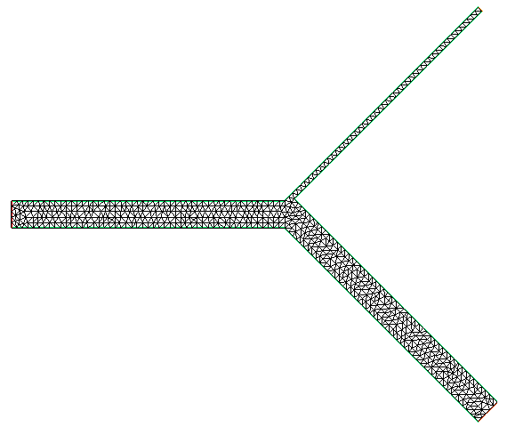
FreeFem++ algorithm for bifurcation mesh generation and generated mesh:
-
bifurcation.edp
-
bifurcation.msh
Overview of the code:
//Parameters
//Dimensions
real nn = 1;        //number of nodes by unit
real l1 = 100.0;    //first branch length
real l2 = 100.0;    //second branch length
real l3 = 100.0;    //third branch length
real d1 = 10.0;     //first branch diameter
real d2 = 10.0;     //second branch diameter
real d3 = 2.0;      //third branch diameter
real alpha2 = -pi/4.;   //second branch angle (-pi/2 < alpha 2 < 0)
real alpha3 = +pi/4.;   //third branch angle  (0 < alpha 3 < +pi/2)
//Labels
int input = 1;      //first branch outlet
int output2 = 2;    //second branch outlet
int output3 = 3;    //third branch outlet
int wall = 10;      //borders

//Mesh
//Initial positions
real x20 = l1 + l2*cos(alpha2);
real y20 = l2*sin(alpha2);
real x30 = l1 + l3*cos(alpha3);
real y30 = d1 + l3*sin(alpha3);
real x60 = l1 + l2*cos(alpha2) + d2*cos(alpha2+pi/2);
real y60 = l2*sin(alpha2) + d2*sin(alpha2+pi/2);
real x70 = l1 + l3*cos(alpha3) + d3*cos(alpha3-pi/2);
real y70 = d1 + l3*sin(alpha3) + d3*sin(alpha3-pi/2);
//Lengths 6 and 7
real a = d1 + l3*sin(alpha3) + d3*sin(alpha3-pi/2) - l2*sin(alpha2) - d2*sin(alpha2+pi/2);
real b = l2*cos(alpha2) + d2*cos(alpha2+pi/2) - l3*cos(alpha3) - d3*cos(alpha3-pi/2);
real l7 = (a + tan(alpha2)*b)/(sin(alpha3)-tan(alpha2)*cos(alpha3));
real l6 = (b + l7*cos(alpha3))/cos(alpha2);
//Borders
border gamma1(t=0, d1){x = 0; y = t; label = input;};
border gamma2(t=0, d2){x = x20 + t*cos(alpha2+pi/2); y = y20 + t*sin(alpha2+pi/2); label = output2;};
border gamma3(t=0, d3){x = x30 + t*cos(alpha3-pi/2); y = y30 + t*sin(alpha3-pi/2); label = output3;};
border gamma4(t=0, l1){x = t; y = 0; label = wall;};
border gamma5(t=0, l2){x = l1 + t*cos(alpha2); y = t*sin(alpha2); label = wall;};
border gamma6(t=0, l6){x = x60 - t*cos(alpha2); y = y60 - t*sin(alpha2); label = wall;};
border gamma7(t=0, l7){x = x70 - t*cos(alpha3); y = y70 - t*sin(alpha3); label = wall;};
border gamma8(t=0, l3){x = l1 + t*cos(alpha3); y = d1 + t*sin(alpha3); label = wall;};
border gamma9(t=0, l1){x = t; y = d1; label = wall;};
//Number of points
int nnl1 = l1*nn;
int nnl2 = l2*nn;
int nnl3 = l3*nn;
int nnd1 = d1*nn;
int nnd2 = d2*nn;
int nnd3 = d3*nn;
int nnl6 = l6*nn;
int nnl7 = l7*nn;
//Build
mesh Th = buildmesh(gamma1(-nnd1) + gamma2(nnd2) + gamma3(-nnd3) + gamma4(nnl1) + gamma5(nnl2) + gamma6(nnl6) + gamma7(-nnl7) + gamma8(-nnl3) + gamma9(-nnl1));

//Save
//Mesh
savemesh(Th, "bifurcation" + ".msh");
//Parameters
ofstream file("bifurcation" + ".dat");
file << "L1\t" << l1 << endl;
file << "L2\t" << l2 << endl;
file << "L3\t" << l3 << endl;
file << "D1\t" << d1 << endl;
file << "D2\t" << d2 << endl;
file << "D3\t" << d3 << endl;
file << "A2\t" << alpha2 << endl;
file << "A3\t" << alpha3 << endl;
file << "E\t" << input << endl;
file << "S2\t" << output2 << endl;
file << "S3\t" << output3 << endl;
file << "B\t" << wall << endl;

//Display
plot(Th);
Cerebral venous network

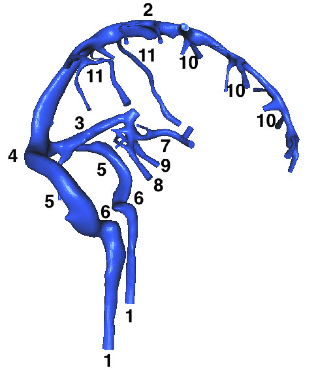
This mesh is obtained using angiographic images (MRI) segmentation, so there is no FreeFem++ code to generate it.
-
cerebral_venous_network.mesh
Some explanations…
The cerebral venous network is composed by - input - veins (7-11) draining the blood into sinuses (2,3) until their confluence (4). The blood then passes into lateral sinuses (5,6) and reaches an extracranial area, composed of the - output - internal jugular veins (1). Here, we give the labels of the veins in detail:
-
internal jugular veins,
-
superior sagittal sinus,
-
straight sinus,
-
confluence of sinuses,
-
lateral sinuses (transverse part),
-
lateral sinuses (sigmoid part),
-
vein of Galen,
-
internal cerebral vein,
-
basilar vein,
-
superior cerebral veins,
-
superior anastomotic veins.